
Convection heat transfer in pin-fin surfaces
1990
0 views
0 downloads
Advisor: Prof.dr. Alpin Kemal Dağsöz
Abstract (EN)
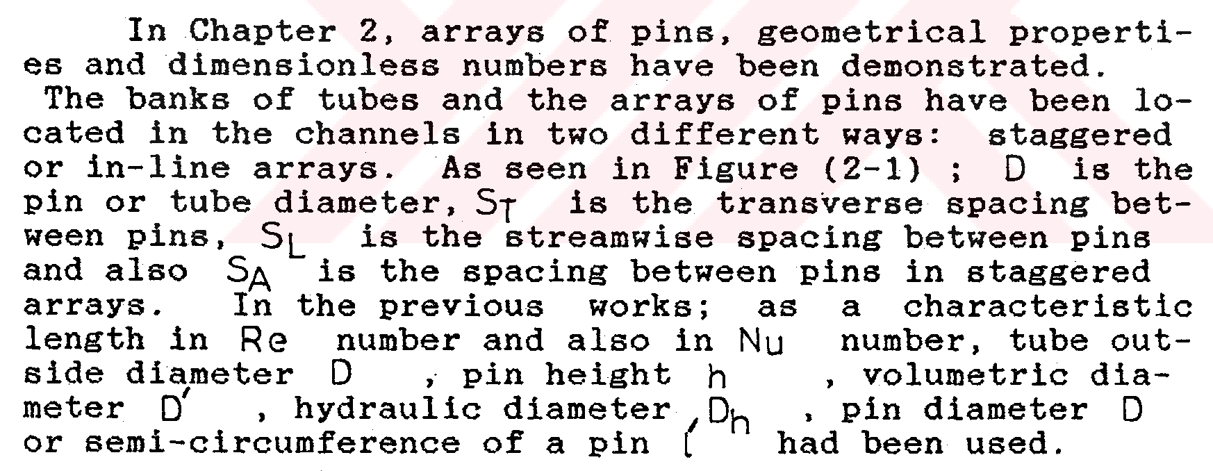
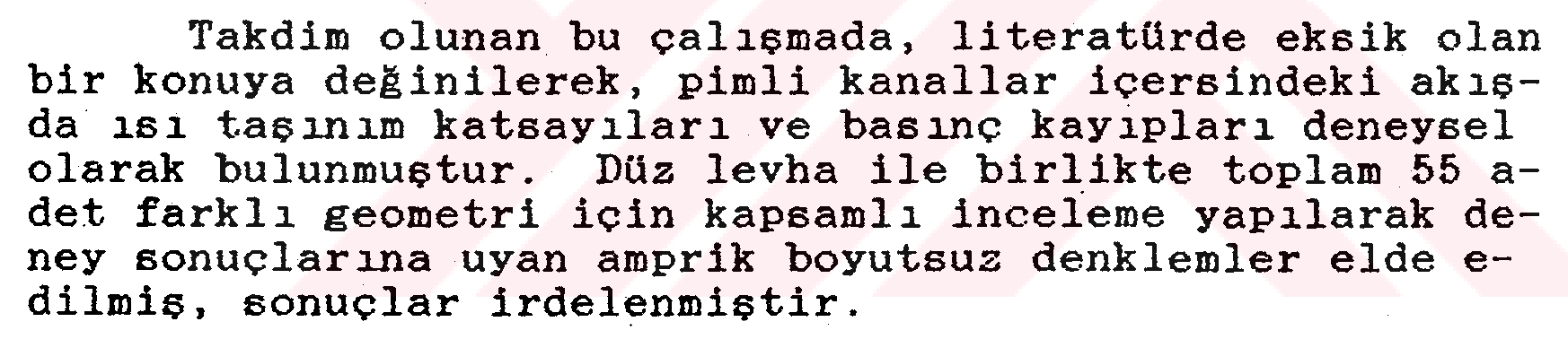
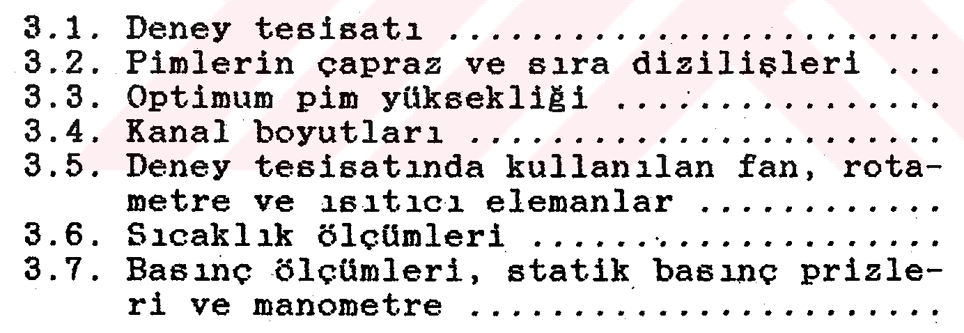
SUMMARY CONVECTION HEAT TRANSFER IN PIN-FIN SURFACES In this study, convection heat transfer in pin-fin surfaces have been examined for filling in the informa tion in literature, partially. In Chapter 1, the advantages and the disadvantages of pin fins relative to the banks of tubes have been shortly told. While the convective heat transfer coef ficients of pin-fin surfaces have been increased, the pressure drop could be decreased in respect of the banks of tubes. In Chapter 2, arrays of pins, geometrical properti es and dimensionless numbers have been demonstrated. The banks of tubes and the arrays of pins have been lo cated in the channels in two different ways: staggered or in-line arrays. As seen in Figure (2-1) ; D is the pin or tube diameter, Sf is the transverse spacing bet ween pins, S(_ is the streamwise spacing between pins and also S/\ is the spacing between pins in staggered arrays. In the previous works; as a characteristic length in Re number and also in Nu number, tube out side diameter D, pin height h, volumetric dia meter D', hydraulic diameter Du. pin diameter D or semi-circumference of a pin ( had been used. The physical properties of fluid and Pr number have been taken from the tables according to the film or average temperature. In Chapter 2.2, the velocity distribution behind the only row of bank of tubes have been calculated the oretically from the Navier-Stokes equations. If the great differences of our geometries from the banks of tubes have been considered, it can be seen that the the oretical solution is impossible. But, only empirical dimensionless equations can be obtained from the experi mental results. - x -In Chapter 3, the test equipment has been recogni zed and it has been shown in Figures (3.1) and (3.2). Experiments were done in a rectangular channel with width, B of 90 mm and height, H| of 46 mm. X. the distance of the test section from the enter is 1.423 m. The length of the test plate, l_ is 130 mm and its width is same as the channel's. Aluminium pins with 5 mm diameter, D and 20, 30, 40 mm height, H2 have been installed on this plate. Two different arrays, in line and staggered, have been tested. We determined the geometry like that: XT = ^=2.00,2.75,3.50 X, =3=.= 1.75,2.25,3.00 D D Xa=-^l=2.0I, 2.46, 3.16 2.23,2.64,3.30,2.47,2.85,3.4 7 ( 1 ) A D XU=^2_=A.OO,6.00,8.00 H D The test plate and the characteristic sizes of the channel cross-section have been shown in Figure (3-3) ; the geometries which were tested, the number of pins and 1 : 1 scaled figures of them have been given in Appendix A Tables (A.l) and (A. 2). Measurements have been done for 55 different geometries also with smooth plate. Constant heat flux was given continuously by attac hing the electric resistance heater under the test pla te. The exit duct has been connected to the fan which sucked the air by means of a vane. Two rotameters for measuring the flow rate have been connected to the out let of the fan. For determining the static pressure drop, pressure taps have been located at the inlet and the outlet of the test section; and also the ends of tabs have rela ted to the inclined manometer containing alcohol with connecting pipes. In the experiment, temperature measurements have been done by 0.5 mm, Fe-Konst. thermocouples. The tem peratures of test section inlet air, test section outlet air, rotameter outlet air, surface of the plate and sur face of the pin are measured. Thermocouples have been welded on the surface of the plate and pins. Figure - xi -(3-3) shows the places of the thermocouples on the test plate, Figure (3-7) shows the places of the thermocoup les in the exit of the test section. In addition to them, the temperature measurement schema with thermo couples have been given in Figure (3-8). In Chapter 4, experiments and data analysis have been explained clearJLy. The flow rates of air read from rotameters V]/V2 (nm^/h), the static pressure drop read from manometer A P (mmSS.) » the temperature of the rotameter exit air 9t ('°G ). the temperatures of the test section exit air 02/---V07 (°C) » the temperatures of the surface of the test plate 08,"v0|o(°C ) and the tempe rature of the test section inlet air 0j/' (°C ) are given in Appendix C. At first, experiments have been done for the turbu lent flow on the smooth plate. In Figure (4-1), the va riations of Nu = hDh/km ; Re = UmDh/vm ( 2 } for the flow on the smooth plate have been compared with the other equations given in the literature. Also in Figure (4-2), the variations of V = (AP/^(Dh/Jou2/2) ; Re = UmiVvm (3)" have been seen, In Chapter (4.4), for the pin-fin surfaces, convec- tive heat transfer coefficients and Nusselt numbers, Nu=h'.D /km ( 4 ) have been calculated. As a characteristic length of Re xiiand Nu numbers ; D, diameter of the pin has been taken. Physical properties of the air '? p. Cp km > Um » vm an<* Pr number have been taken accor ding to the average temperature of the fluid. For the results, the equation like that Nu Pr",/3= A ReB ( 5 ) has been accepted and here, the coefficients A and B have been found by the method of least squares, Dimensionless static pressure drops related to the Re numbers have been given by this equation : Û.P /jo U& / 2 = M ReN ( 6 ) Also, the coefficients M and N have been found by the method of least squares, too. Percantage devia tion, mean deviation and correlation factor have been determined. In Chapter 5, the results of the experiments have been given. For different geometries; the variations of Nu Pr^'3 related to the Re numbers are shown in Ap pendix E, Figures (E. 1),...., (E. 9) and also completely in Figures (5-1) and (5-2). For all the experiments, the coefficients A and B in staggered arrays are listed in Table (5-1) and for in-line arrays they are given in Table (5-2). The variations of ^ related to the Re numbers are shown in Appendix F, Figures (F.l),(F.9) and also completely in Figures (5-3) and (5-4). For all the experiments, the coefficients M and N in staggered arrays are seen in Table (5-3) and for in-line arrays they are given in Table (5-4). - xiiiFor the 550 experimental data in 55 different geo metries, the deviation in per-cent, ha is : -21.480%* (N'J Pr Experiment ~(A Re >,l00 ^)S.06S % ( 7 ) (Nu ^Experiment The mean deviation is given like that +1.247 % £ a £ +9.257 % ( 8 ) The deviation in per-cent for the pressure drops (AP/oUm/2). t_(M ReN) -34.601./.£ £ SXpe' 'ment -100 £+24.817% ( 9 ) (AP/pu2,/2) f m experiment The mean deviation : + 1.121% £ a £ + 10.020% ( 10 } Correlation factors for all the conclusions : r =0.99 ( 11 ) The results of the experiments computed by PC-e computer are given in Appendix D. If we compare the results of convective heat trans fer coefficients with eachother, it can be seen that : - xiv -The convective heat transfer coefficients in pin- fin surfaces are greater than the coefficients of the smooth surfaces. For the least Xy(2.00) and the shortest pin's height X|_|(4.00), in the geometry of XL= 175, 2.25,3.00 hstaggered < hin-line ( 12 ) Because, in staggered arrays, air is resisted and can not be easily entered between the pins. But, in in line arrays, air enters between the pins and washes them. As Xt, Xi and X[_) increases; hfn-line < hstaggerad ( 13 ) For the greatest distances ( Xt = 3.50/X,=2.25,XH-6.00 )and (XT=3.50,XL=3.00,XH::4.00,6.00 ) j hin-line S hstaggered ( 14 > While Xj, X[_ are constant in both staggered and ^-line arrays, as X|_) (4.00,6.00,8.00 ) increases, so the convective heat transfer coefficient will be grea- xn th ter In the geometry of Xt=2.75,X|_=3.00,X|_| = 8.00 in both staggered and in-line arrays, the value of h is the greatest. Xj=2.00 is the narrowest cross-section trans verse to the flow; so air can not enter adequately bet ween the pins. Xj =3. 50 is the widest cross-section trans verse to the flow. Here, air enters between the pins, but can not wash sufficiently them, so h decreases. The most optimum result is taken in the geometry of XT = 2.75 If we compare the results of static pressure drop with eachother, it can be seen that : - xv -Ap.. > AP il. ( 15 ) APstaggered > APin-line ( 16 ) While Xj and X^ are constant, as Xı increases, (APs^oggerecj -"AP'ın-line ) decreases; while Xy and X[_ are constant, as Xh increases so (AP5taggered -APin-Une) increases; while X[_ and ^ are constant, as Xy increases, so (A P~+"""^__,j - A P-.. ^ ) increases. vti staggered " in-line ' In both staggered and also in-line arrays, while Xy, Xr are constant, as the height of the pin(Xj-j) increases, so the static pressure drop will be greater for the reason of more resistance formed against the flow. Also in both arrays, while X|_, X}-) are cons tant, as Xy increases so A P decreases. As X[_ increases in staggered arrays, so A P dec reases; but there isnt't any important change for in-li ne arrays. In this work, the diameter of the pin is continu ously constant. It can be thought that the convective heat transfer coefficient will be more greater by chan ging the pin's diameter or using the rough pins in dif ferent cross-sections or drilling holes on the surfaces of the pins. In addition to them, it shouldn't be for gotten that the static pressure drop musn't increase anymore. - xvi -
Author
Dr. Ahmet Korhan Binark

How to Cite
Ahmet Korhan Binark (Doctorate thesis). Convection heat transfer in pin-fin surfaces, 1990, Istanbul Technical University.
Figures & Images (223)



Keywords
License
Tüm Hakları Saklıdır
This work is shared under the specified license terms.
More theses from Istanbul Technical University
- Investigation Of Stretching Effect With Mixed Finite Element Formulations For Laminated Beams And Plates(2023)
- Classification of anemia using data mining methods: An application(2015)
- Removal and recovery of platinum group metals through anode slimes of moebius electrolysis(2015)
- A study of design approaches to Istanbul's city halls based on space syntax theory(2015)
- A II. German Empire project: From Kaiser Wilhelm Monument to German fountain(2015)
- Uzaktan algılama verilerinin yersel ölçümlerle entegrasyonu ile toprak tuzluluk haritalaması; Aşağı Seyhan Ovası, Adana, Türkiye(2015)